 Image reference
Solar PV protection

PV & DC surge protection
WILLING supplies surge protective device options for solar PV DC strings, combiner boxes, inverter DC inputs and electrical protection panels.
Use this page to compare application context, SPD selection factors, installation workflow and the meaning of key electrical parameters before requesting a model-specific datasheet.
Reference status: Values transcribed from supplied product images require confirmation against the current model datasheet and certification scope.
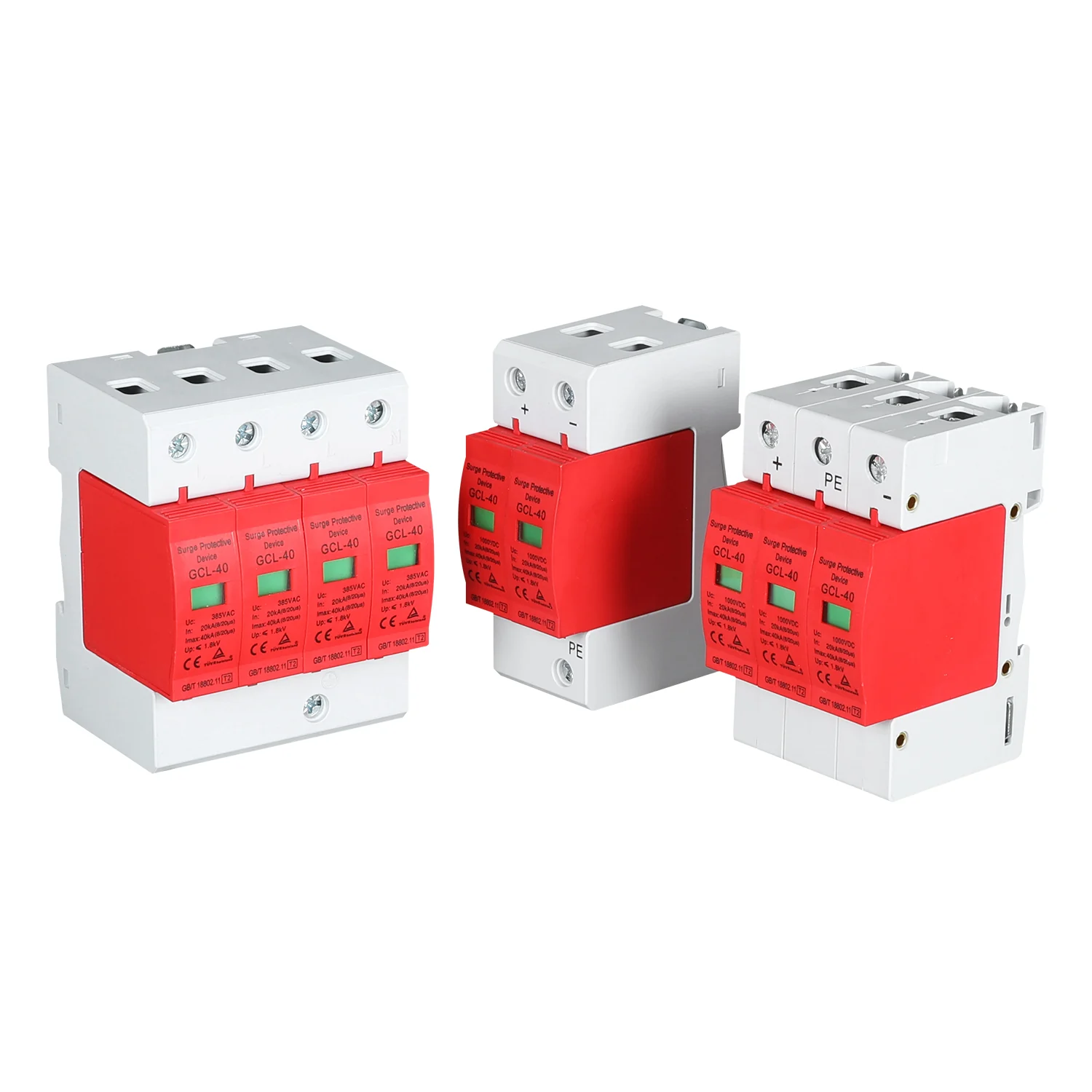
SPD product range
Confirm circuit type, maximum continuous voltage, pole configuration, discharge ratings and documentation before final product selection.
Image reference
Solar PV protection
 Image reference
Three-pole arrangement
 Configuration reference
Four-pole arrangement
Engineering parameters
Important: These values are not presented as a universal WILLING series specification. Request the current datasheet, connection diagram and document scope for the exact model being evaluated.
Application workflow
Final device selection should be completed by a qualified electrical professional using the project single-line diagram, risk assessment and local requirements.
Identify the circuit side first. A PV-rated DC SPD and an AC SPD are not interchangeable.
Check maximum continuous operating voltage, PV open-circuit conditions, system topology and environmental limits.
Coordinate protection at the combiner box, inverter input or AC distribution point according to the project design. Use the PV combiner box engineering guide when reviewing enclosure-level DC protection.
Keep connection paths short and follow the approved wiring diagram, earthing design and manufacturer instructions.
Include visual status, terminal condition and replacement criteria in commissioning and scheduled maintenance.
Standards and compliance review
A standard reference is not a product compliance claim. Verify valid test reports, declarations and the exact model scope before approval.
| Reference | Scope | Engineering use |
|---|---|---|
| IEC 61643-31:2018 | Requirements and test methods for SPDs used on the DC side of photovoltaic installations. | PV DC product and document review. |
| IEC 61643-32:2017 | Selection and application principles for SPDs connected to the DC side of PV installations. | System selection, placement and coordination review. |
| IEC 61643-11:2025 | Requirements and test methods for SPDs connected to AC low-voltage power systems. | AC-side SPD evaluation. |
The supplied product images display GCL-40, GB/T 18802.11, T2, CE and TUV-related markings. Treat all markings as reference until the current certificate, declaration and exact model coverage are confirmed.
For destination-specific project review, use the Australia solar DC resource, the UAE solar DC resource, or the global market engineering directory. These pages organize project questions and document requests; they do not represent blanket product approval.
Engineering questions
A surge protective device limits transient overvoltage and diverts surge current away from sensitive equipment. It supports protection of PV strings, combiner boxes, inverter inputs and AC distribution equipment, but it does not replace overcurrent protection or system earthing.
The installation point depends on the PV system architecture and risk assessment. Common locations include the DC combiner box and inverter DC input. Conductor routing, coordination and earthing must follow the project design, applicable standards and the SPD manufacturer's instructions.
Uc is the maximum continuous operating voltage. In is the nominal discharge current. Imax is the maximum discharge current for a Type 2 SPD under the stated test waveform. Up is the voltage protection level measured under defined test conditions.
Match the SPD to the circuit side, voltage, current characteristics and system topology. Use a PV-rated DC SPD on the photovoltaic DC side and an AC-rated SPD on the AC distribution side. Do not use an AC-only SPD in a PV DC circuit.
Not always. SPD type and coordination depend on lightning exposure, the external lightning protection system, cable routing, installation category and the project risk assessment. Some projects may require Type 1 or combined Type 1 and Type 2 protection.
Inspect the status indicator, terminals, protective conductor path and signs of heat or damage during scheduled maintenance and after significant surge events. Replace a failed module according to the manufacturer's instructions and verify the circuit is isolated before service.
Project inquiry
Include the circuit side, maximum voltage, pole configuration, quantity and destination market so we can prepare the correct model reference.